
Edited by Gary Komar rev: 3/2022
Get printable version(.pdf)
Get printable scales (.jpg)
Get printable Foot height table (.pdf)

As I mentioned on our About Us Page, we have a Logan Pro Joiner (Model F300-2) for nailing our frames together. There are four different things that one must adjust before using it, but there are only two parameters, moulding width and moulding thickness, used to make those adjustments. I made four new scales to put on your joiner to make your life easier.

I will discuss how to apply these scales to your joiner and how to use them as we look at each adjustment in more detail. I will discuss them in the same order introduced in the Logan manual.
V-nail Slider Block Spacing
The Old Scale
The slider spacing scale measures the distance between the two V-nails (except that scale always places the V-nails ⅜” closer together than the distance on the scale). The manual tells you to set the slider block to match the reading on the vise scale, which measures the moulding width. This measured width is the total moulding width minus the width of the rabbet that holds in the glass and is the width you should use for setting these parameters. We will refer to this measurement later as “W.” Logan states that if you set the V-nail slider to this width, each V-nail will be ¼” from the outside and inside ends of the miter joint. That is not true.
which reduces to

or appoximately

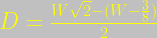
by dividing the whole expression by the square root of two, the average distance to the nearest edge would be
appoximately 
The New Scale
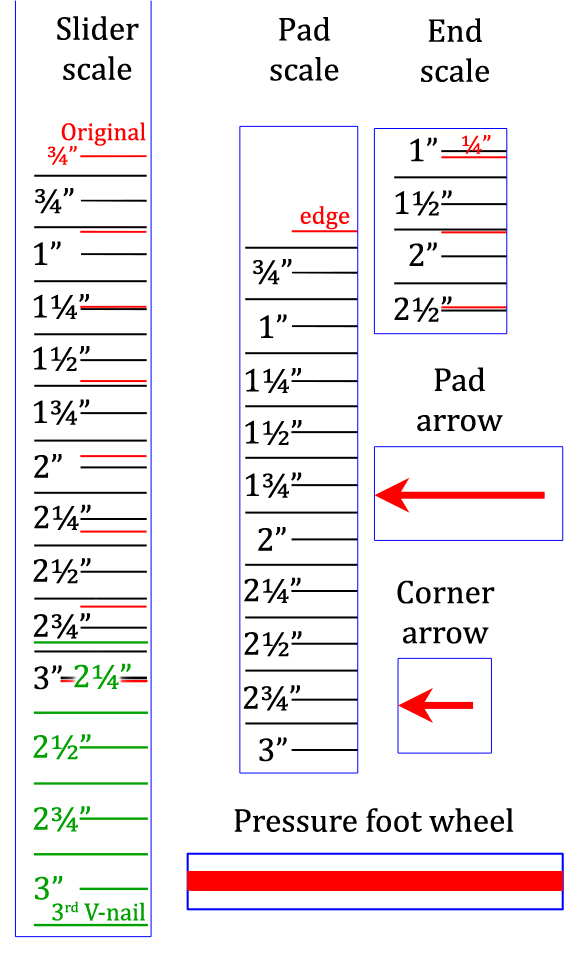
If I were using only one V-nail, I would put it in the center of the miter joint. I would conceptually divide the moulding in half if I needed two V-nails and put a V-nail in the center of each half. If the moulding were wide enough to require three V-nails, I would divide the moulding into thirds and put the nail in the center of each third. (If there is a structural engineer in the house or someone that knows a better place to position the V-nails, I’m listening.) The numbers on my new scale (labeled “A” in Figure 1 and “Slider scale” in Figure 2 above) represent the moulding width W, not the gap between nails. Using my scales will put the two V-nails 25% of the joint length in from each end of the miter joint.
Attaching the scale
If you download the printable file of the scales (you can click the link just below the title of this article), you can print them either on plain paper or even a 2″ by 4″ label. The red lines and numbers shown in Figure 2 correspond to the existing Logan scales. After printing, you should compare the distances between the red lines to the same distances on the Logan scale to be sure your printer/software didn’t arbitrarily change the dimension of the scale. Then cut along the blue lines. The black lines and numbers represent the moulding width (W).
To accurately place the slider block scale, place the edge of the sliding V-nail block on the ¾” mark on the existing scale. Then place my scale on the opposite side of the slider so that the red ¾” mark is lined up with that same edge of the block (as shown in Figure 3).

Using the scale
To use these scales to press two V-nails into the moulding, place the edge of the V-nail block on W, as you read it from the vise scale, in the regular (black print) section of the slider scale. Then set the V-nail Corner Spacing Stop and the Lever Adjustment Block to W (as discussed below). Then make all other adjustments as prescribed in the manual and lower the pressure foot onto the moulding.
If You Need Three V-nails
If you needed to press three V-nails, my system divides the width into thirds and puts a nail in the center of each section, which puts them at 16.7%, 50%, and 83.3% of the miter length. So you would press the two nails closest to the outer edge of the frame by following the above instructions to adjust the components at all three scales to a value of 2/3 of W. For example, if the measured moulding width were 3″, you would adjust all W settings to 2″. Press the two V-nails.
Then put the third V-nail into the sliding nail holder only (leaving the fixed nail holder empty). Set the Slider Scale to W (3″) in the green section on the right side of that scale. Then set the pressure foot for 4/3 × W (which would be 4″ in this case) or as close to that as the lever adjustment block will allow. Leave all other adjustments the same. Press the last nail.
If You Only Need One V-nail
If, for some reason, you only wanted to use one V-nail, start as you would for three V-nails, but instead of putting both nails in, you just want the one in the sliding block (at 50% of miter length). After pressing it in, forget about the third nail. For example, if W were 2″, you would set everything for 2/3 of 2″, or just over 15/16“, put the nail in the sliding nail holder, and pull the lever handle.
Other options
If you would prefer to set the V-nails as you did before (or even if you would like to put them where Logan said you were putting them before), then an additional set of scales could easily be made using the moulding width as the setting instead of actual nail distances. Then you would only have to read the vise scale and set everything automatically, without further calculations. Although simplicity was the motivation for this effort, having multiple alternative scales is beyond the scope of this article. But if you need help with that, let me know.
V-nail Corner Spacing
The scale (labeled “B” in Figure 1) is located on the back of the left slider guide (as you face the joiner from the front). The original scale goes from ¼” to ¾” in ⅛” increments, which is a slightly larger range than the V-nail Corner Spacing Stop (on the back end of the right guide) can use. That scale shows the distance the outside V-nail will be from the corner of the moulding, but it reads more than 1/16” smaller than the actual distance. For example, the position of the V-nail slider in Figure 4 will put the outer V-nail 5/16” in from the corner of the moulding (as measured along the miter).
My scale would go to the right of the original scale so that both scales are still available. After placing the scale, measure the distance between the ¼” mark on the old scale and the red ¼” mark on the new scale. That is the distance you should place the arrow from the back end of the slider. It should be ⅛” above the bottom edge of the slider so you can see it above the slider guide.

Pressure Foot Placement
For simple moulding profiles that do not require the black moulding spacer, I created a scale (labeled “C” in Figure 1) based on moulding width W to help center the pressure foot over the moulding.

Cut out the Pad scale (see Figure 2) and place it to the left of the lever adjustment block (the same side as the Pro Joiner label, as shown in Figure 5 above) so that the red edge line is on the edge of the top plate, as shown in Figure 1. To place the arrow, slide the lever adjustment block all the way back (in Figure 5, that would be to the left). Then place the arrow above the edge of the top plate.
When setting up the joiner, put the arrow over the W measurement on the scale. It is that simple. Some mouldings may require a manual adjustment to the pressure foot placement. Our 1½” high stretcher moulding, for which W is 1″, has a ⅜”-wide ridge along the outer edge of the top of the moulding. The simplest way to handle that is to pretend there is a symmetrical ⅜”-wide ridge beyond the inner edge of the moulding; add ⅜” to W, and set the pressure foot to that 1⅜” value. On the other hand, if that moulding had such an obstacle only on the inner edge instead of the outer edge, you would subtract that ⅜” from W and set the pressure foot to the resulting ⅝” value.
Adjust Foot Height
This is the setting based on moulding thickness instead of moulding width (W). The size of the V-nail used is also a factor, but that is also based on moulding thickness. I have not yet found a good way to attach a scale for this adjustment, but I have made a table that relates the moulding thickness to the number of threads that should be exposed above the lever height wheel, based on 12 threads per inch.

You could download the .pdf file (look just below the title of this article), and you could even attach it to the top plate of the joiner (as shown as D in Figure 1). With the wheel all the way up, you could cut out the Pressure foot wheel box and attach it to the wheel, as shown in Figure 7, in a position where the red line will be convenient for viewing. Then it will be easier to count revolutions as you lower the foot into place.

To set the foot height, rotate the wheel down from the top the number of rotations listed in the table. The lever handle should be just a little above horizontal when the moulding first contacts the V-nails and the same angle below horizontal when the lever handle bottoms out. The precise angle is not critical here, so you could just follow the instructions in the Logan manual. They are pretty straightforward but could take a little longer.
Odds and Ends
Stacking V-nails
We haven’t ever deliberately stacked V-nails, as Logan discusses on Page 6 of their manual, but we have tried a different brand of V-nail that is longer than the longest Logan V-nail. We use the AMP (a Fletcher Company) 15mm Mitre-Mite V-nail (their longest), as mentioned in Figure 6, for our 1½” stretcher moulding. It works well on our Logan joiner.
Glue First
We used to apply glue to the miter joint and then immediately put our frames together with the joiner. After the beginner’s luck wore off, we noticed that the joints weren’t as tight as we would have liked. Then I stumbled onto a couple of websites that suggested gluing the frame together using a band clamp and then V-nailing the corners after the glue dries. One of those references was an old article on the Logan Graphics blog. We haven’t had any problem with that since.
That’s All, Folks
That should about cover it. If you have any questions, shortcuts, or other suggestions for improvement, let me know in the comment section below. And if not, then thanks for listening.
Don't get discouraged; it may take over 24 hours for your comments to appear.